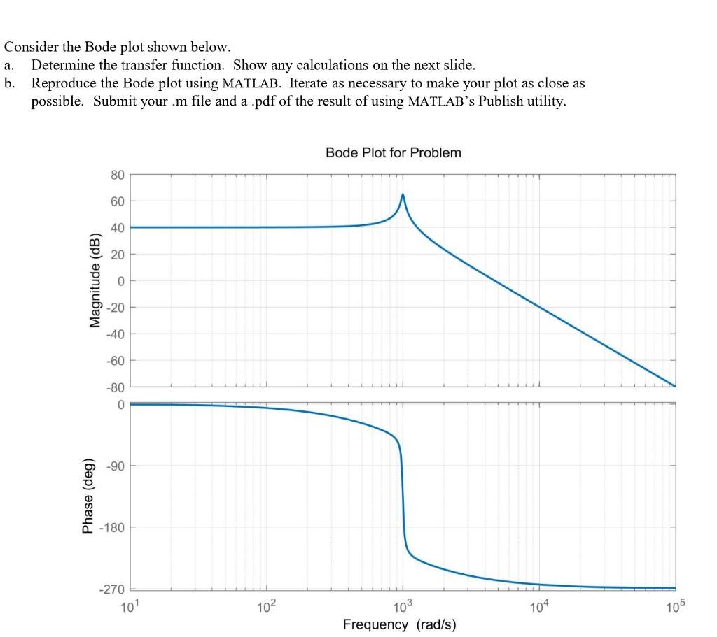

The distance below 0dB at this point shows the system gain margin.At some point obtain amplitude response.Find the point, where system phase response crosses -180.Which will cause marginal stability of a system. It can be described as an increase in the open-loop system gain |GH (jω)| when system phase is at 180. Phase and gain margin are usually measured from open loop response and cannot be obtained from the frequency response of a closed loop system directly. This distance can be measured in terms called phase margin and gain margin. How far -1 is from open loop transfer function GH (jω) measures the stability of a system. The characteristic equation of a typical system can be written as, It is the frequency at which amplitude ratio becomes 1 or log modulus of transfer function becomes 0. It is the frequency, where phase shift becomes -180 o. There are certain terms, which we need to familiar with to fully understand the bode plot. Wn = 2*pi*fn % Natural frequency conversion in rad/sįig.6: Plot for Second Order System Special Terms Here, we implemented the bode plot of a second-order network for the comprehensive understanding of the readers. Which means that phase plot would be a straight line with -90. $G\left( j\omega \right)H\left( j\omega \right)=K$ For gain factor K, the bode-plot is obtained as: We will discuss above elementary factors one by one: Gain factor KĪ constant K may be considered as complex number expressed in polar form with magnitude K and angle 0. The Bode plot or diagram of a transfer function can be constructed by combining the transfer functions of following elementary factors. In bode-plot, low-frequency asymptote (that is ω>1/T) cut off at 0 decibels (dB) line where ω=1/T, that is the frequency called corner frequency or break point. A third advantage results from the introduction of logarithms, thus reducing the process of multiplying two transfer functions to addition.A second advantage is that this technique is feasible for lower frequencies, where measuring the phase difference between input and output signals is difficult.One apparent advantage of the bode diagram is the relative ease with which it is obtained.At times, the magnitude of a transfer function is referred to as gain and the corresponding plot as a gain plot. The magnitude of the transfer function is expressed in decibels (dB), the phase in degrees and the common parameter of frequency is plotted on a logarithmic scale in radians.


 0 kommentar(er)
